OptiLayer enables calculating and plotting a large variety of spectral characteristics:
The spectral characteristics are calculated for the design currently loaded into the memory. Spectral characteristics can be calculated and plotted in spectral mode as well as in angular mode. The design cross section is represented by the design bar showing layers in different colors, the number of layers N and the overall thickness Th of the coating. If a target is loaded, the corresponding merit function value MF is presented on the bottom of the plot. |
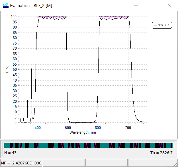
Fig.1. Transmittance of a 43-layer bandpass filter. Total thickness of 2926.7 nm is shown on the bottom right corner. |
 Fig. 2. Transmittance of a 26-layer narrow bandpass filter at 0 and 30 degrees. Adding reflectance at 30 degrees to the plot. Fig. 2. Transmittance of a 26-layer narrow bandpass filter at 0 and 30 degrees. Adding reflectance at 30 degrees to the plot. |
It is possible to plot different spectral properties on the same plot. It is easy to add a new plot or remove a plot.
The setting are available through: Evaluation Plot –> right mouse click –> Plots If you compose several spectral characteristics measured in different units in one plot (for example, reflectance and phase), the second right axis appears automatically. |
| Axis can be set using OptiLayer tool available through Evaluation Plot –> right mouse click –> Axis (Fig. 3) or using the standard Chart Editor available through Evaluation Plot –> right mouse click –> Chart Editor (Fig. 4). | |
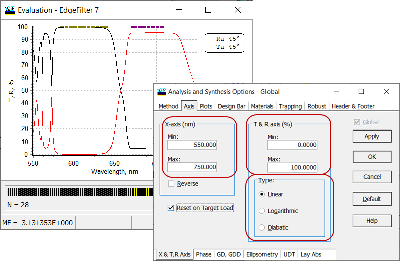
Fig. 3. Settings of axis for spectral characteristics of an edge filter. In Type field, it is possible to choose between linear, logarithmic and diabatic scales. If Reset on Target Load check box is checked, axis will be recalculated automatically according to loaded target. |
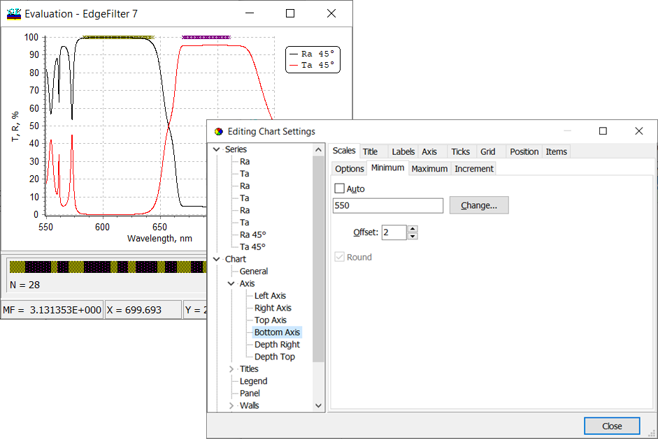
Fig. 4. Settings of axis for spectral characteristics of an edge filter using standard Chart Editor. |
| OptiLayer calculates spectral characteristics of different configurations: coatings on semi-infinite substrates, coatings on substrates with back side, double-sided coatings. The corresponding settings can be found in General Information window available through View. | |
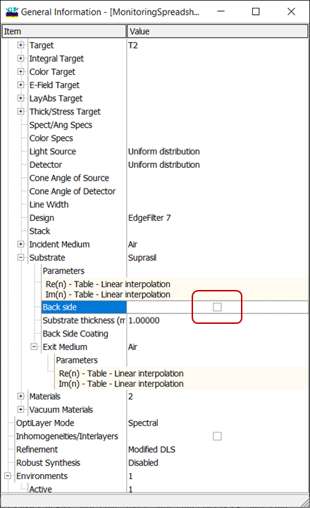
Fig. 5. Settings corresponding to a coating on a semi-infinite substrate (the structure is shown in Fig. 6). If the angle of incidence (AOI) is \(\alpha\), then the light exits at the angle \(\beta\) connected with \(\alpha\) through Snell’s law: \[n_a \sin\alpha=n_s \sin\beta \] Important: Back-side reflectance is calculated so that the light exits the coating at the same AOI \(\alpha\) (Fig. 6). Example: \(n_a=1, n_s=1.44, \alpha=45^{\circ}\). The light enters the back side at AOI \(\beta=29.4^{\circ}\). If you need to calculate the back-side reflectance so that the light enters the back side of the substrate at AOI=\(\alpha\), you need to recalculate the corresponding AOI \(\alpha\) using Snell’s law. Example: \(n_a=1, n_s=1.44, \beta=40^{\circ}\). Then AOI \(\alpha=67.7^{\circ}\). |
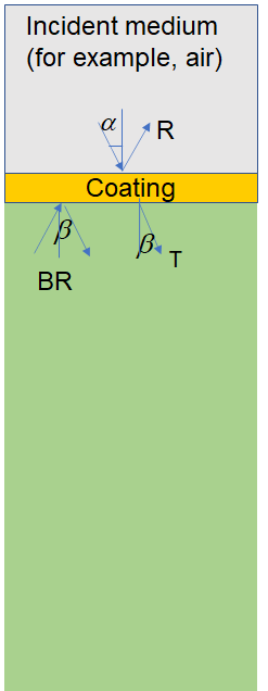
Fig. 6. Schematic of a multilayer coating on a semi-infinite substrate. |
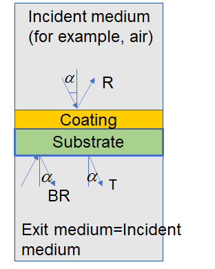
Fig. 7. Schematic of a multilayer coating on a substrate. If exit medium is the same as incident medium, the light exits the substrate at the same AOI \(\alpha\). The light enters the back-side of the substrate at the same AOI \(\alpha\). |
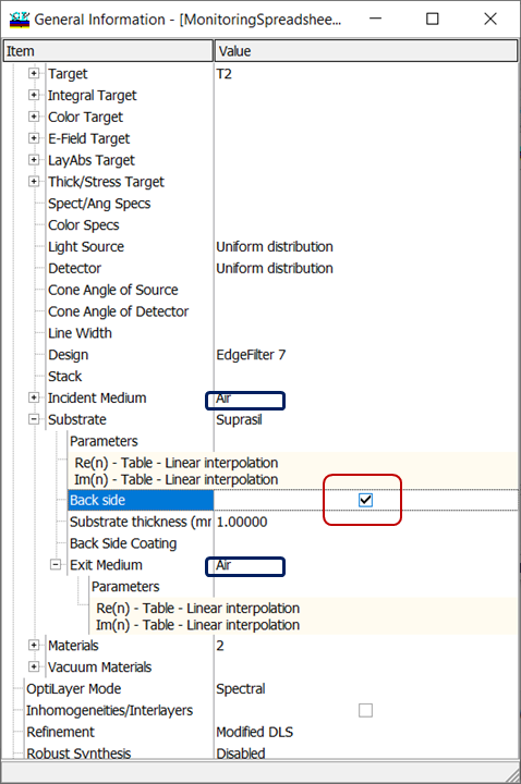
Fig. 8. Settings corresponding to a coating on a substrate (the structure is shown in Fig. 7). Exit medium coincides with incident medium (Air). |
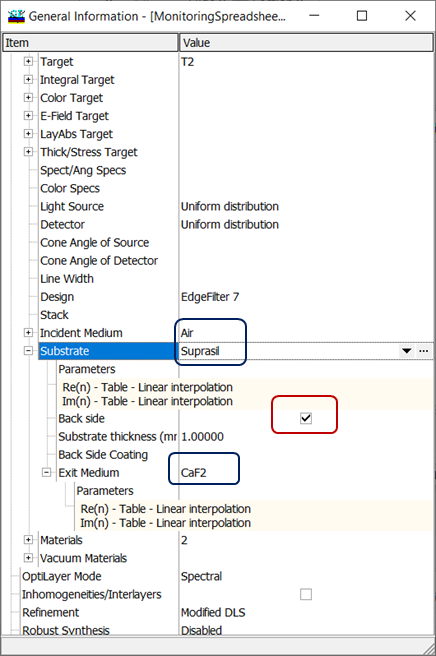
Fig. 9. Settings corresponding to a coating on a substrate (the structure is shown in Fig. 10). Exit medium (CaF2) differs from the incident medium (Air). If the exit medium differs from the incident medium, the light exits the substrate at AOI \(\beta\). The light enters the back-side of the substrate at the AOI \(\beta\). |
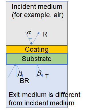
Fig. 10. Schematic of a multilayer coating on a substrate. Exit medium and incident medium are different. If the angle of incidence (AOI) is \(\alpha\), then the light exits at the angle \(\beta\) connected with \(\alpha\) through Snell’s law: \[n_a \sin\alpha=n_{e} \sin\beta \] Important: Back-side reflectance is calculated so that the light exits the coating at the same AOI \(\alpha\) (Fig. 10). Example: \(n_a=1, n_s=1.44, n_{e}=1.65, \alpha=45^{\circ}\). The light enters the back side at AOI \(\beta=25.4^{\circ}\). If you need to calculate the back-side reflectance so that the light enters the back side of the substrate at AOI=\(\alpha\), you need to recalculate the corresponding AOI \(\alpha\) using Snell’s law. Example: \(n_a=1, n_s=1.44, n_{e}=1.65, \beta=30^{\circ}\). Then AOI \(\alpha=55.6^{\circ}\). |
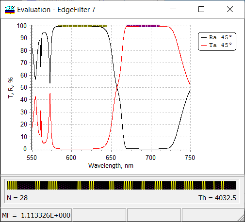
Fig. 11. Reflectance and Transmittance of a 28-layer edge filter at AOI 45 degrees. The substrate back side is not taken into account (see Figs. 5 and 6). |
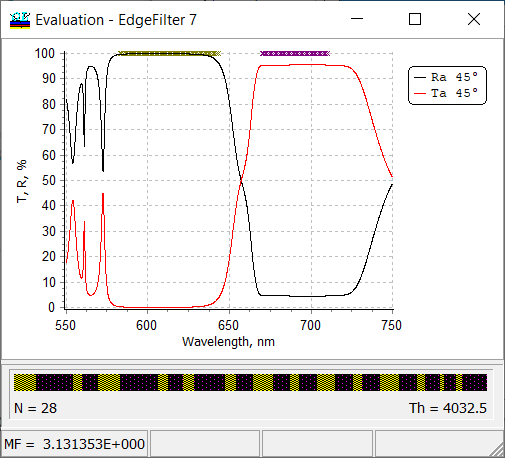
Fig. 12. Reflectance and Transmittance of a 28-layer edge filter at AOI 45 degrees. The substrate back side is taken into account (see Figs. 7 and 8). |
| In OptiLayer, you can open multiple evaluation windows to plot
(i) different spectral characteristics of a design; (ii) in different spectral ranges; (iii) with different types of axis; |
|
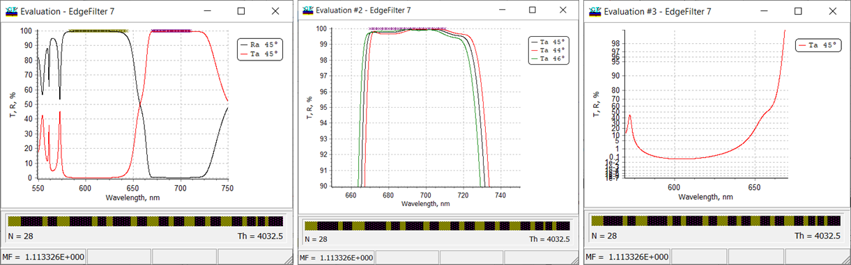
Fig. 12. Multiple evaluation windows corresponding a 28-layer edge filter: R/T at AOI 45 degrees in the entire spectral range of interest (left panel); only transmittance in the high-transmittance range at AOI 44,45, and 46 degrees (middle panel); transmittance in low transmission range in diabatic scale. |
|
| OptiLayer allows you to calculate various phase properties of multilayers. In the case of phase calculations (\(\varphi\)), you can specify radian or degrees as units:
Configuration –> Settings –> Units –> Phase limits. In the case of degrees, you can choose between \([-180^{\circ};+180^{\circ}]\) and \([0^{\circ};360^{\circ}]\) limits. In the case of radians, you can choose between \([-\pi;\pi]\) and \([0;2\pi]\) limits. Also, you can calculate phase as continuous plots (Figs. 13, 14).
|
|
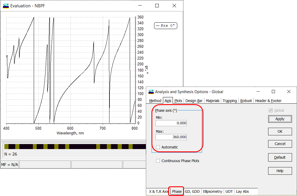
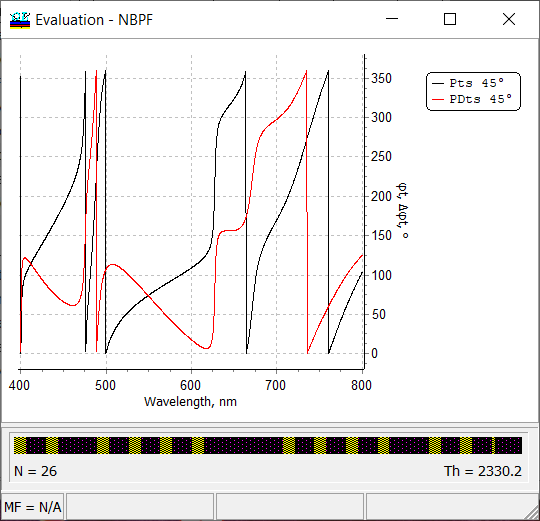
Fig. 13. Phase in degrees of a 26-layer narrow bandpass filter. |
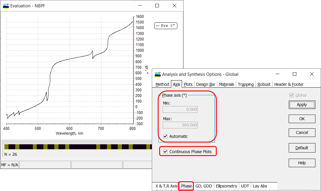
Fig. 14. Phase in degrees of a 26-layer narrow bandpass filter presented continuously. |
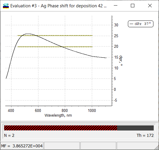
Fig. 15. Differential phase shift on reflection of a two-layer Ag-Al2O3 coating. |
OptiLayer allows you to calculate differential phase shift on reflectance and transmittance (\(d\varphi r, \; d\varphi t)\) that is the difference between phases in s- and p-polarization cases:
\[d\varphi=\varphi^{s}-\varphi^{p} \] |
| (New! Starting from 14.57).
OptiLayer allows you to calculate the phase difference on transmission \(\Delta\varphi t\). This value is calculated as a difference of phases at the substrate boundary between the wave propagated through a coating and the wave propagating the same distance in the incident medium replacing the coating (see schematic in Fig. 17): \[ \Delta\varphi t=\varphi_A^{(1)}-\varphi_A^{(2)} \]
Fig. 16. Phase and phase difference on transmittance calculated for a 26-layer narrow band pass filter. Exit medium is air. |
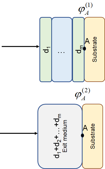
Fig. 17. Schematic of the phase difference calculation. |
| OptiLayer calculates Group delay (GD) and group delay dispersion (GDD) for the transmitted and reflected light, both polarizations, all angles of incidence.
Optilayer performs calculations using analytical formulas! If multi-coating mode is activated, OptiLayer evaluates GD and GDD of separate coatings (in a complementary pair or in a double-angle configuration) as well as of the corresponding coatings combination.
|
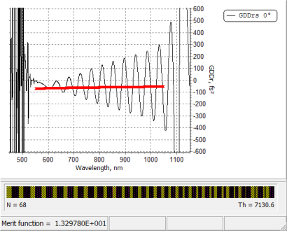
Fig. 18. Group delay dispersion of a 68-layer dispersive mirror. |
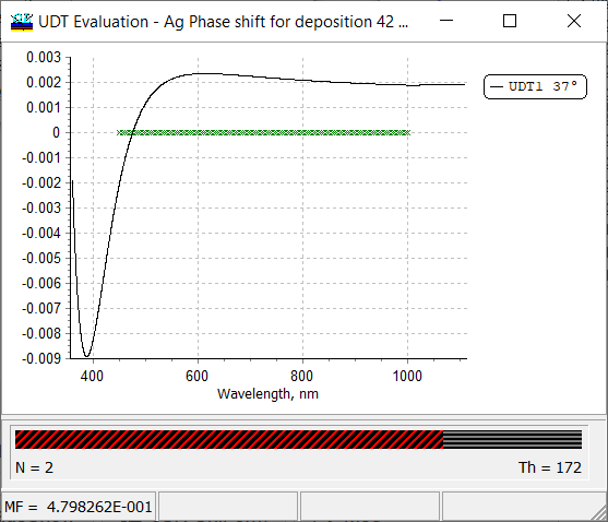
Fig. 19. UDT spectral characteristic, that is difference between s- and p-polarized reflectance \(R^{(s)}-R^{(p)}\) of a two-layers Ag-Al2O3 coating. |
In the case, if a User-Defined-Target (UDT) is specified, the UDT spectral characteristic can be evaluated and plotted in a separate window (Fig. 19) available through:
Analysis –> More… –> UDT |
| In OptiLayer, you can evaluate absorptance in separate layers.
The evaluation setting and the plot are available through: Analysis –> More… –> Layer Absorptance |
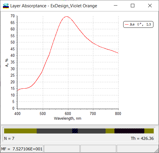
Fig. 20. Absorptance in the third layer (L3), that is an Ag-layer, of a coating reflecting different colors from its front and back sides. |
| Calculations of spectral characteristics can be performed in angular mode.This mode can be set in General Configuration window: Configuration –> Settings (Fig. 22).
In this case, spectral characteristics are calculated in an angular range for separate wavelengths (Fig. 21). |
|
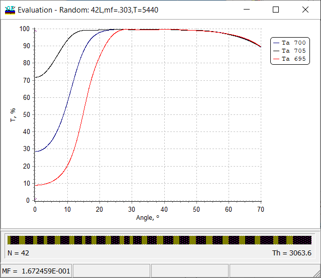
Fig. 21. Transmittance of a cold mirrors calculated in an angular range from 0 to 70 degrees for transit wavelengths 695 nm, 700 nm and 795 nm. |
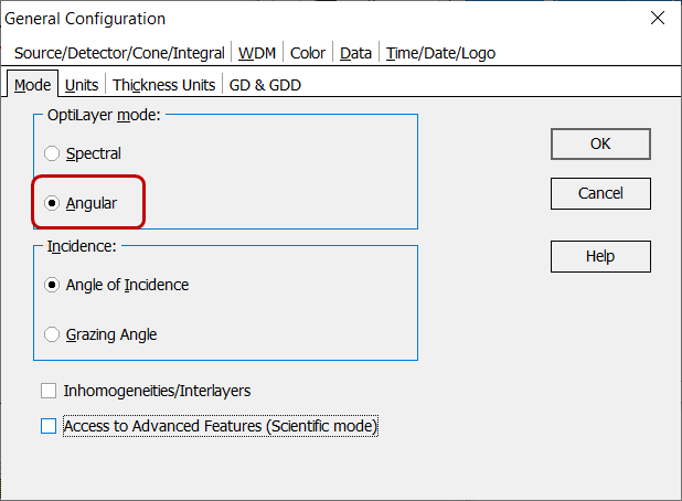
Fig. 22. Transfer to the angular mode in General configuration window. |
| OptiLayer evaluates and plots Ellipsometric Angles as functions of the wavelength or angle of incidence.
Limits and units for \(\Delta\) angle can be specified in the same way as for phase, i.e. through General Configuration window. |
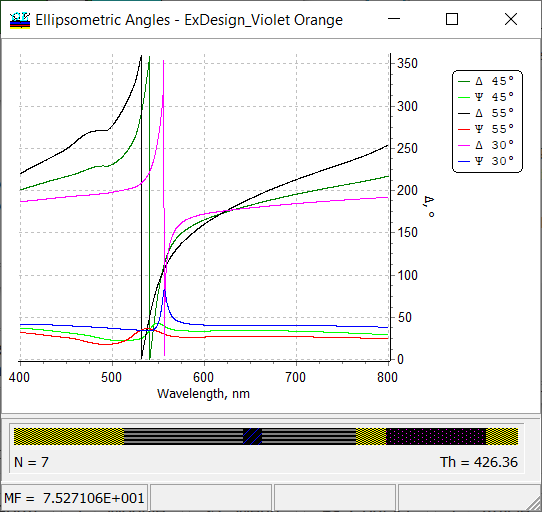
Fig. 23. Ellipsometric angles \(\Psi\) and \(\Delta\) of a seven-layer metal-dielectric coating. |
OptiLayer provides user-friendly interface and a variety of examples allowing even a beginner to effectively start to design and characterize optical coatings. Read more…
Comprehensive manual in PDF format and e-mail support help you at each step of your work with OptiLayer.
If you are already an experienced user, OptiLayer gives your almost unlimited opportunities in solving all problems arising in design-production chain. Visit our publications page.
Look our video examples at YouTube
OptiLayer videos are available here:
Overview of Design/Analysis options of OptiLayer and overview of Characterization/Reverse Engineering options.
The videos were presented at the joint Agilent/OptiLayer webinar.